Studer 169 Console Linked Pair Restoration/Installation Odyssey
| July 29th, 2012Last summer we were fortunate enough to acquire a pair of circa 1978 Swiss-made 10-input Studer 169 consoles. They belonged to the company that runs the Toronto Blue Jays’ stadium and were likely used in a remote truck.
A few months before all this we’d built a pair of Studer 169 EQ clones for our 500-series lunchbox. (Reverse engineering, PCB design and documentation by Audiox; quality PCBs available for sale from Gustav in Denmark). We really loved the sound of these things (perhaps more than our lone API 550A EQ) and so began the lusting over the genuine article. But we never honestly expected we’d find a Studer 169 that we could afford.
Originally we intended on buying just one of the two consoles but the seller threw in the second one as a parts machine—luckily it was nearly complete and didn’t require too much work to get back in working order. The only serious issues were that the mute functionality was broken (this ended up being a ground plane short) and two mic inputs sounded weak and thin (it was a transformer problem and Neutrik, the OEM, still makes the pieces and they’re not outrageously priced). The fine folks at Audiohouse in Switzerland had the odds and ends that weren’t included in the ‘spare’ console (some fader knobs, odd size bolts, handles, etc).
Tho the previous owners kept things mostly stock, they did make the downright strange decision of changing the power input to a A-gauge 1/4″ jack (like a guitar). Perhaps it was part of a prank or hazing ritual and they never changed it back? They also added incandescent lamps to all the meters (we ending up disconnecting these lamps because we concerned about the power supplies being overly taxed).
Throwing tantalums
We began by replacing the electrolytic and tantalum capacitors in all the cards. In all there were 20 channel strips; 4 master units; 2 monitor units; 2 DC-to-DC converter cards; and 2 external power supplies. Yeah there were a lot of capacitors to replace. The image below shows a small sliver of our workbench surface at the time.
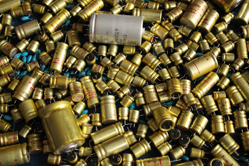
A picture of our workbench showing some of the *many* electrolytic and tantalum caps that we replaced on our Studer 169s
The original Frako electrolytics looked pretty rough (lots of gunk oozing out) but nearly all of them measured within spec in terms of capacitance. We don’t have an ESR tester so replaced them all as a precaution. Replacing the Tantalums seemed to fix some sporadic switch clicks and noises.
The mystery jack
In the course of cleaning and re-capping we decided to remove a metal plate on the bottom of one of the consoles. Underneath, it revealed a printed circuit board had been installed in the bottom of one of the desks. The manual told us that this ‘coupling print’ board was designed to allow the two mixers to connect together and function a single 20 input 2 bus unit.
We weren’t able to see any evidence on the Internet of anyone trying this out, so we checked in with Garfield, our neighbourhood Studer technician. (Aside: if you’re in Montreal and need Studer stuff fixed or any professional analog tape machines looked after, we can give you his number). Gar deemed it an intelligent bit of engineering and assured us he was certain Studer wouldn’t have included if it didn’t work well (rather persnickety those Swiss). Very good to hear. The next step was finding the elusive connector.
The manual only specified a Studer part, which was unobtainable (natch). After hours wasted clicking through Swiss, German and Liechtensteinian electronics parts catalogs, someone on a messageboard gave us a vital clue—”try Hirschmann or Preh.” Hirschmann it was. It was the same part (WIST 10) as the remote connector for the Revox A77 deck.
The Hirschmann was used for the ‘extension console,’ the main console only required a relatively common 50 pin D-sub (DB50) connector. Pictured below are the DB50 plug, the evil-to-solder Hirschmann WIST 10 plug, and the Hirschmann jack.


Gar’s eureka moment
Garfield came upon a brilliant idea after looking at the console interconnection schematics: make the linkages selectively ‘breakable’ through patch bay wiring. The genius of this idea is that it allows the linked consoles to act more like a 4-bus/4-aux unit than the 2-bus/2-aux. This along with a guy in Mexico and a guy in Croatia’s great ideas for an non-invasive direct-out mod, meant that the linked Studer 169s could easily function as our main console (the only catch is that you have to give up the ‘signalling’ functionality where opening faders could trigger switches; this is mostly useful in broadcast situations anyhow but we could have wired up a pretty sweet console-actuated light show). While you could always use the insert sends on these boards as direct outs, we wanted to keep these inserts pre-EQ and have the direct outs be post-EQ, post-fader but pre-mute. The gain structure is such that both the direct out taps and insert sends are at considerably lower nominal levels compared to the bus outs. But in practice it’s no problem as the the mic and line amps have copious gain and much greater clean headroom than we’re used to.
We were able to perform the direct out mod while vacationing in a farmhouse. Our friend Tessa of the great band Brave Radar took the pic below of our work area for doing the mod; no soldering was required, just crimping and wire stripping.
Adieu, old friend (or ‘I don’t really see—why we can’t go on as three?’)
Our reliable, loyal Tascam M520 couldn’t have seen it coming. One doesn’t expect older, mightier, more tranformer-y Swiss twins to show up as usurpers, does one? As much as we liked the Tascam, the Studers were an inarguable step up—from semi-pro to pro. And we all know the prefix ‘semi’ is the cruelest of qualifiers (cf. the band Semisonic, semi-erections, etc.).
It would have been great to keep the m520 as a sidecar but we really needed the space. Plus the Studers were requiring us to switch over from a mostly unbalanced -10dBv setup to a balanced +4dBu standard so there would have been some interfacing headaches. The Tascam ended up selling really quickly. It went to a good home.
Patch 22: Solder of misfortune
We were using unbalanced TS and RCA patch bays previously (along with Fostex 5030 matchboxes for interfacing some bits of gear) so now was the time to install some tiny telephone/bantam bays we’d accumulated over time. We hadn’t quite anticipated just how hellish it would be to completely change over all our patch bays. If anyone else is in a similar situations, our advice would be: be very sure your new console is immensely superior to your old one before contemplating a changeover that would require redoing all your bays—it’s going to be more expensive and more labourious than you expect. And you’ll be huffing more noxious fumes than Evan Dando at a Viper Room lock-in. [Tip: Pass the time with podcasts (Jonny Trunk’s OST Show on resonance FM is our fav; here’s the very wonderful Trish and Jam of Broadcast guest appearance episode) and audiobooks (Henry Rollins unintentionally hilarious reading of “Get in the Van” is an unheralded comedy classic)].
The patch bay installation took at least one pound of solder (you’re welcome, lungs); much help from Garfield; untold hours of soldering/crimping and wire stripping drudgery; a painful $$$ investment in hookup wire, EDAC multi-pin connectors (we highly recommend these), XLR, TRS, and banana connectors; plus pricey bantam/TT patch cables. One of our bays was ADC punch style which required a specialized tool as well (part# QB-4). We would have gone quite mad if we didn’t spring for a Paladin Stripax automatic stripping tool.

Paladin Stripax: kept us out of Bedlam
It was worth it though: The balanced TT/bantam setup allowed hitherto unknown luxuries like: normalled connections; mult blocks; and polarity turnarounds. Garfield, the aforementioned Studer tech, kindly hipped us to classic studio patch bay layout standards (e.g. normalling aux sends to reverb; half-normalling sends and returns; etc) which we had been quite ignorant of beforehand. Here is the layout we ended up going with:
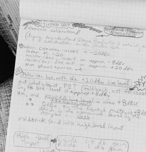
Calibrate good times, c’mon?
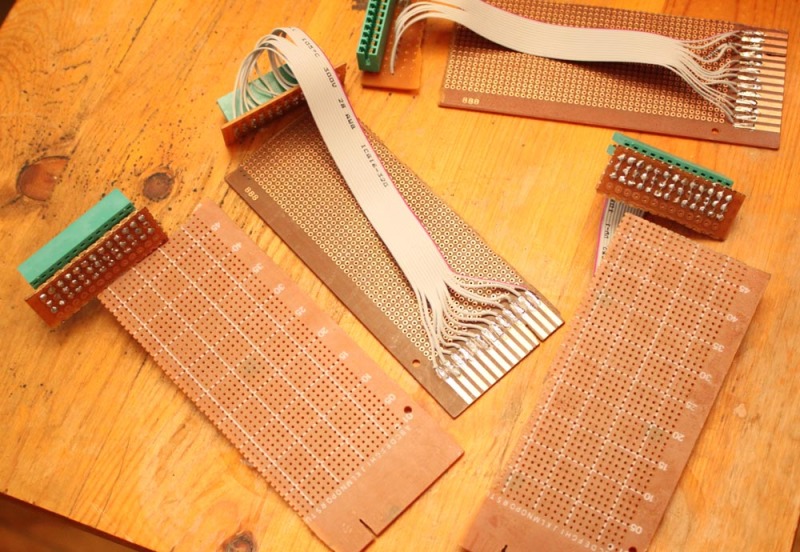
These consoles seemingly hadn’t been in use for a while so we had to put them through a pretty extensive cleanup/calibration. The very thorough service manual made it a relatively straightforward, if lengthy, process. We didn’t have the required extender cards so we had to build our own. The consoles themselves had 4 unused edge connectors so we desoldered them. We didn’t have any luck finding metric prototyping cards with correct pitch, so we used these .1″ pitch perfboards from RP Electronics; for the edge connectors we found some little perfboards that were close enough (we had to bend the pins) at Addison Electronique, our local surplus shop. It was a kludge and wasn’t pretty but we figured out a place to file the key slot so that there was no chance of anything shorting. And hey, they worked. The guy in Croatia also DIY’d some extenders. He had the right parts and did a much, much tidier, vastly superior job.
The built-in limiters were the trickiest things to calibrate—an oscilloscope is a must here. They seemed to be impossible to align correctly until we saw a very helpful tip about replacing leaking diodes (once again from the kindly Croatian guy). Some of the open frame trimmers also needed replacing (these were the only components we were disappointed in quality-wise).
After this was done we got everything up to spec and the console was pressed into service. Only one gremlin cropped up: one of the DC-DC converters failed. This was easily bypassed and replaced with a reasonably priced Power One linear PSU module (model HAA15-0.8-AG).
Done!
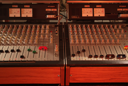
The image below show the consoles in action. We built that little dual VU meter box (with old Burlington Instruments meters) to help us get used to the very different PPM metering on the Studers. We also made the oak sides and front covers (the original owners had them rack mounted).
Further reading
This Croatian fellow wrote up a detailed account of how he restored a Studer 169:
Restauration of STUDER 169 console
This person decided to build a partial Studer 169 from scratch:
Diary of a very complex audio build – Studer 169
Studer kindly put the full documentation for the 169/269 series of consoles here. Apart from the service manual, a number of tech bulletins are also available.








 |
|