Blog posts filed under: Gear

We built a pair of PRR 176 stereo vari-mu compressors a couple years ago and we really love them. They’re maybe a little quirkier and less predicable than 1176 rev D FET limiters or LA2As, but on the whole they’re probably our favourite compressors–especially for vocals and clean guitars. They’re also very capable on stereo bus duty. Boards are no longer available for sale but un-built PCBs are frequently listed on the GroupDIY Black Market. We recently did a few modifications to our PRR 176s so I thought I’d do a writeup.

µ Oughta Know

Vari-mu, variable µ, or ‘tube’ compression is one of the major dynamic range compression circuit categories, the other main types being: Optical (LA2A); Diode Bridge (EMI TG12413, Neve 2254); FET (UREI 1176, early Allison Gain Brain); Pulse Width Modulation (Pye); and VCA (dbx 160, SSL, later Valley Gain Brain, most modern compressors). Each approach (and each circuit implementation) imparts its own sound though differing time constants, non-linearities and distortion products that are sometimes quite euphonic.

Prior to the invention of compression, dynamics were either controlled by manually adjusting levels or by performers positioning themselves nearer to or farther from the mic. Difficulties might arise with unpredictable talent: One thinks of the MGM crew charged with capturing the lion’s roar. Similarly, early Elvis Presley sessions allegedly employed an assistant to grab the King by his shoulders and physically vary his distance to and from the microphone based on musical dynamics. (Other reports say Elvis’s voice went through an RCA vari-mu compressor set to a gentle 2:1 ratio).

I believe vari-mu was the earliest electronic automatic gain control technology. Data are sketchy but as far as I can find, the Western Electric 110 compressor from 1937 is the first such unit. You can read a circuit description on page 563 of the December 1937 issue of Wireless World. Some say the Langevin Progar was developed earlier but took longer to come to market. Click here for a rough timeline of compressor development.

Unfettered Progress

The induction of the 1176 FET compressor in 1967 sounded the death knell for variable µ compression development. FETs are capable of faster attack times (which was crucial for the broadcast clients looking to get the loudest possible signal without over-modulating). The slower, more transparent optical compression technology cöexisted with vari-mu since the 1950s, but the new FET types (and the roughly contemporary diode bridge type) seemingly bested the old tube-based units in every important way: faster, quieter, wider control range, more reliable, and of course cheaper build costs. Thus development of new vari-mu types ground to a halt by the late 1960s.

Actual working engineers never quite gave up on tube compression. John Fry of Ardent studios called the Universal Audio 176 his compressor of choice for Radio City. And the Fairchild 670’s reputation grew to where it was probably the most coveted outboard gear unit in the world (last time I checked, they were going for $45K USD) .

Manley released their stereo Variable Mu compressor in 1994 (which I think was the first new major production tube compressor since they fell out of favour in the late-60s/early 70s). A few years later the Thermionic Culture Phoenix (supposedly based on the EMI-modified Altec 436) came out. Both of these units were very nice-sounding but neither differed much from vintage designs (not necessarily a bad thing but it made them very expensive).

Then in 2003, a guy who goes by PRR (don’t know his full name or background–I gather that he’s a professor of some sort) conceived a cheap-to-build modern vari-mu and gave his schematic and circuit description away for free. PRR’s design was a novel approach emphasizing the use of cheap, easily obtainable components (like ubiquitous 12AU7 tubes for gain reduction). As far as I can tell, his was the first to dispense with a vacuum tube side chain signal. Interestingly, Rein Narma, the Fairchild 660/670 designer, says in this interview that he’d have used a solid state side-chain if it was available to him.

Abe Chapman of AC Sound Studios came up with his circuit boards as a sort of cross between the PRR Vari-Mu compressor design and elements of the classic Universal Audio 175/176, such as employing a 6BC8 tube for gain reduction. Plus he added a few modern refinements, like: stereo or dual mono operation, bypass, and a switchable side-chain hi-pass filter (to reduce pumping when used on a stereo bus).

We didn’t tally the costs of building these compressors, but I’m quite sure it was under $2000 for all four channels. The priciest components were the audio transformers. Enclosures were probably the next most expensive items. We used budget, powder-coated steel 2RU cases with aluminum front panels. Working with steel is pure torture so I’d highly recommend getting an all-aluminum chassis if you can afford it.

Rev 1 Build Notes

Abe’s first circuit board for the PRR 176 was already pretty well worked out. The only major problem was that the power supply on the main board would add noise to the circuit. The relatively easy work-around was building a simple Veroboard circuit for power supply rectification and filtering.

Rev 1 off-board power filtering mod

The circuit also lacked a bypass. This was relatively easy fix by lifting one leg of the side-chain capacitor and installing a front panel switch. Because this capacitor is in parallel with the side-chain high-pass filter cap, you need to engage the HPF switch for bypass to work. It’s a bit inelegant but it works. Note that this is a compression bypass, not a hard bypass. Hard bypass requires extra circuitry and relays. The advantage to this ‘soft-bypass’ approach is that you can use it as a line amplifier (e.g. extra clean gain after a mic preamp). The disadvantage is that you can’t do quick A-B comparisons between compressors.

Rev 1 soft bypass mod

For the Rev 1 we used Swedish Lundahl transformers for input; UK-made BBC/Sowter units for interstage (a really critical component for this compressor); and Canadian Hammond 1:1 600 ohm transformers for output. We initially used the optional IC balanced output but after some testing we decided we preferred the transformer outputs.

Lundhal LL1540 Transformer

Sowter BBC type 4257 Transformer

Hammond output transformer

Everything worked quite well from the start except for the odd incident of thermal shutdown. We discovered that the tube filament regulator’s heat sink was inadequate. The fix was simple: mount the regulator IC to the case.

Rev 2 Build Notes

PRR 176 Vari-Mu Rev 2

The Rev 2 PCB set provided a separate board for its power supply. Again everything went well right off the bat except for the tube filament regulator getting too hot (again, mounting it to the case fixed the problem).

Rev 2 PSU board, note header connection to chassis-mounted heater regulator

For this unit, we used less expensive American-made Edcor input transfers, Lundahls for the interstage, and again Hammonds for the output. This transformer array gives a subtly different sound.

We socketed the capacitors for the side-chain high-pass filter in order to experiment with different values. We ended up liking Abe’s default choices (tho an extreme hi-pass made for an interesting de-esser effect).

Side-chain HPF capacitors

Like the 176 and 1176, this compressor uses the input signal to set the compression threshold. We decided to do a simple modification to make this a bit easier to use in the real world. We fitted multi-turn trimmers to a switch and mounted them to the front panel and then ran the switch to the circuit board. This gives us a quick, calibrated high or low threshold (I’ve always found the 1176’s threshold impractically high for typical console ‘send’ levels). With stereo linking engaged, the circuit uses the channel 1 attack and release controls for both channels (input and output levels must be carefully matched for each side).

PRR 176 switchable threshold

Calibration etc

The calibration procedure is pretty straightforward. Here’s Abe’s description:

Trimmers:
1k VR3, VR9 ….this balances the power between the 2 halves of the 6BC8 tube. Helps if you don’t have a perfectly balanced tube.
100R VR1,VR4 adjust for minimum “thump”
1k VR5, VR2 Control Meters, Power on, let it warm up for a bit (10 minutes or so) turn until meters read “0” gr.

There are a couple different ways to do the ‘thump’ calibration (which is, by far, the most crucial). The simple way is to feed a 20hz clean sine wave, dial in a decent amount of gain reduction and adjust for the least distorted waveform on an oscilloscope. A slightly more sophisticated approach is to feed the compressor gated bursts of high frequency (20KHz is good) and adjust for minimum thump. Here’s a good overview of both approaches.

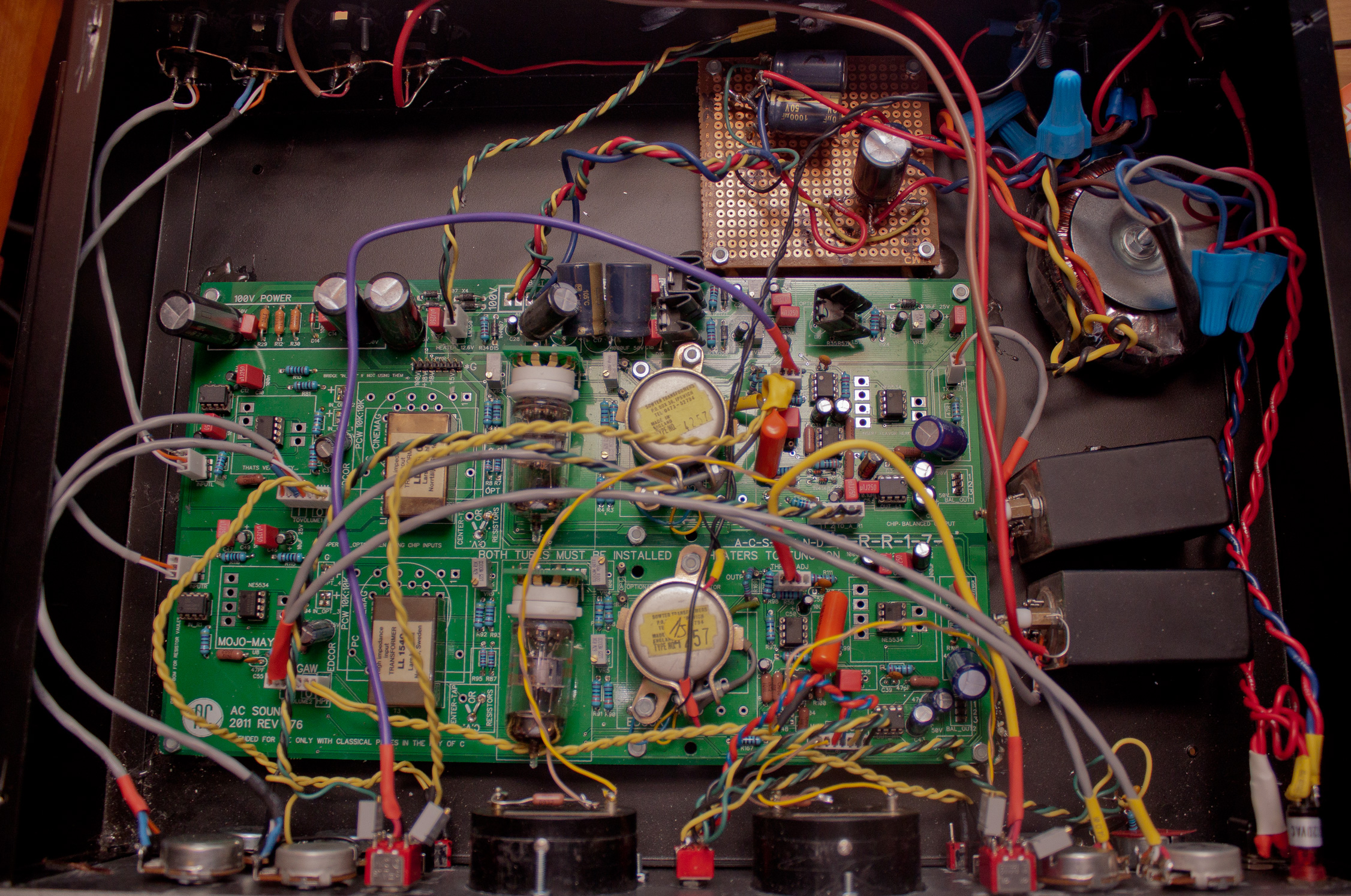
We did encounter a several 6BC8 tubes had to be rejected because they weren’t balanced well enough to work in the circuit (so it’s wise to factor in the cost of buying some extra tubes). As you can see by the photos, we’re no experts at wire dressing but the compressor is very quiet and we’ve had no problems with oscillation despite the extra all the extra wiring from our modifications.

American RCA 6BC8

Canadian RCA 6BC8

On our Rev 1, the meter calibration wouldn’t quite go to zero with our NOS Weston meters (found at Leeds Radio in New York).

Weston type 506 1mA meter

The simple solution was to add a 1Kohm resistor in series.

Weston Meter zero set mod resistor

We tried to measure the attack and release times with software but didn’t have much luck. The compression ‘knee’ is quite soft so it’s difficult to say when you’d deem it to be ‘in gain reduction’. It looks like it’s a bit faster than the 176’s 100 µsec attack time (but noticeably slower than the 1176’s 20µsec maximum) but I’d need to research measurement standards to know for sure. The settings aren’t fool-proof: even when well-calibrated, it’s possible to get some ‘thumping’ noise if the very fastest attack and release times are used on bass heavy material.

The front-panel finish was done with Tremclad ‘hammered finish’ spray-paint (a terrible product with noxious fumes and lumpy, inconsistent coverage properties) and the lettering done with old Decadry transfer sheets (an unbearably tedious job) and protected with clear nail lacquer (we tried two brands: ‘OPI Start to Finish’ which sucks and almost destroyed the already sketchy paint job; the other type called ‘Mavala top coat’ worked OK). If you hate metalwork as much as I do, circular Neutrik Powercon connectors are a small mercy to save yourself the agony of drilling a rectangle for a standard IEC inlet. Amateur metalwork generally involves breathing in nasty particulate matter, countless splinters, and hours of filing. If you can afford it you’d be best off getting Front Panel Express or a local engraver to finish your chassis.

Neutrik PowerCon connector: Mercifully easy to drill.

Further reading

See the original build threads for much more information (including schematics, bills of materials, wiring guides, etc.)

PRR-176 Rev 1 Build Thread

PRR-176 Rev 2 Build Thread

PRR-176 Rev 4 Build Thread
In case you were wondering: there is no Rev 3.

Early this year we scrounged together the cash to get the parts to build a D-LA2A, a very clever and well-documented project where you can make a pair of LA2As on a single printed circuit board.

The LA2A, if you’ve never encountered one, is a circa-1965 compressor or levelling amplifier. It’s one of those classic pieces that never really fell out of favour in pro audio circles. It only has two knobs (gain and peak reduction) and it’s pretty much impossible to get a bad sound out of it.

If you’re not familiar with audio compressors, they’re basically devices designed to lessen the differences between loud and soft audio signals, smoothing out erratic dynamic shifts. The LA2A’s is historically significant because it was the first truly effective ‘optical’ compressor, meaning it controls gain through electroluminescence and photo-resistance. As the audio signal intensifies, an electroluminescent panel glows; this in turn causes a coupled photo-resistive circuit to trigger gain reduction.

My description is horribly crude, so I scanned these pages from the Audio Cyclopedia by Howard Tremaine, which explains the LA2a’s workings clearly and accurately (click them to enlarge); for LA2A aficionados like us, discovering this document evokes Young Frankenstein: 

The LA2A as explained by smart people

Audio Cyclopedia LA2A part 1

Audio Cyclopedia LA2A part 2

Audio Cyclopedia LA2A part 3

For the truly curious, a person named Christian Sugar created this very nice circuit deconstruction:

Christian Sugar’s LA2A circuit deconstruction

Twin peak reduction: the making of a sequel

We’d already built a single LA2A clone in a 3RU chassis using a Drip Electronics PCB a year earlier, and we’ve used it on pretty much every session since. When we read about the DLA2A we were pretty impressed that that Volker, the German fellow who designed the circuit board, was able to squeeze the two of these comps onto a single compact board without compromising anything. And as a bonus, LA2As work quite well stereo-linked as bus compressors.

The [Silent:Arts] D-LA2A printed circuit board


We decided to go for it and ordered everything so they’d arrive in time for the Christmas holidays. The Printed circuit board and a custom toroidal power transformer came from the guy in Germany who thought the whole thing up [Silent:Arts] (he’s a classy fellow, the package only took about a week to ship from overseas and he tossed in some gummy bears); we got the audio transformers from Edcor in USA (which are much cheaper than the British Sowter transformers we used for the Drip LA2a); the tubes were from thetubestore.com in Hamilton; we found a Par-Metal aluminum chassis on eBay; we got stereo-matched T4B opto-attenuator units from Drip in Santa Fe; the rest of the parts were either from a local surplus shop or Mouser Electronics in Texas (we’re kinda glossing over this: prepare for hours of staring at catalog pages on computer screen to order all the resistors, capacitors and other bits and bobs—it’s the second most annoying part of all this DIY electronics stuff, next to only the dreaded metalwork).

The first sines of trouble or Doctor, it hertz when I do this

The build was quick and straightforward. It only took a day-or-so (except for the metalwork–that was annoying and tedious and we have no real aptitude for it) and everything worked from the first power up. There was only one bug–at very high gain levels it would self-oscillate. Even though it didn’t interfere with normal usage (it would only oscillate at impractically high levels) this still really stuck in our craws. We needed to do something about it.

To begin troubleshooting, we checked it out with the ‘scope. As the pic below shows, it was pretty clean sine wave at 30Khz. Lacking much in the way of repair know-how, this didn’t really tell us anything that we could act upon. It did, however, allow us to take a picture of a nice ‘m’ shape.

At higher gain settings, our D-LA2A was oscillating at about 30kHz.

In keeping with our astoundingly foolish troubleshooting ways, we decided to change a bunch of things at the same time. This assured us that even if we set things right, we’d never know for sure exactly what fixed it.

The first thing we did was add a socket to C4, the capacitor that governs the high frequency response. This let us choose the precise cap value to get us a flat response up to 20KHz without allowing too much ultrasonic (>20KHz) signal to pass through (which could contribute to that oscillation). It turned out that we had to use different values for the two channels to get them to match exactly (100pF and 250pF).

We decided to add a socket for C104/C204 (C4 in the original LA2A schematic). This capacitor plays a large part in determining the frequency response.

Next, we completely re-wired the whole thing. Lead dressing is a black art to us. We had the leads fairly long intially so that we could run them far away from any hum-inducing parts. With the re-wiring, we decided to go the route of keeping the wire lengths as short as possible (our theory being, there’s less surface area for interference to creep in). Once again, thanks to our lunkheaded and impatient try-a-bunch-of-things-at-the-same-time troubleshooting ways, we’ll never know 100% for sure if this made any difference. It did at least seem to lower the noise floor a bit.

Along the same lines, we also set about rearranging the audio transformers. Previously, they were tidily and symmetrically laid out. We changed them so they’re as far away from each other as we could fit. We used bolts stuck to the chassis with JB Weld for mounting. (Aside: JB Weld is good stuff–Freelove Fenner would totally be up for writing a jingle for the company. If you’re reading this JB Weld person, let’s talk turkey).

Another minor change we made was to remove the neon bulbs that are used for regulating the gain reduction metering and replace them with zener diodes. The zeners are allegedly quieter and more stable.

Here’s the innards of our D-LA2A. They had been a little bit tidier before but we shortened nearly all the leads in the course of troubleshooting the oscillation issue; the veroboard in the back is just there because we accidentally bought PCB mount pots for the zero set.

The last major change we made was modifying the circuit to use 12AY7 tubes rather than 12AX7s in the V1 position. This lowered the maximum gain slightly, but the AY7s are nicer sounding (subjectively, natch) and less trouble-prone tubes. This required a few resistor changes in the circuit. This was all first suggested by a knowledgeable fellow named CJ in California.

The good news is that all these changes (or one of these changes−who knows?) worked! Our D-LA2A is now quieter and completely immune to self-oscillation. Shown below are a few pictures of our build.

Topless pics:

Here’s our finished D-LA2A with the lid off. We labelled it with Letraset.

Here’s a closeup of the switches and the VU/Gain Reduction meter. The meters were made by Sifam UK.

Channel 2 controls in detail. We used Davies Molding phenolic knobs. The truly observant might notice the third knob, not present in the original: this is the side-chain high pass filter which is an internal adjustment on the real ones (intended to make the unit more sensitive to high frequency peaks, for protecting FM transmitters from overmodulating). We find it handy for bus compression duties (less ‘pumping’ from bass).

Mighty Mite II Tube Tester. This is from about 1960. We were surprised that Davies Molding is still in business and still selling the exact same phenolic knobs on this guy.

We used a Neutrik Powercon connector for the AC inlet rather than an IEC. They’re way easier to install because they only require drilling a circular hole, rather than the annoying square hole for IECs.

D-LA2A zero set; the pots are for zeroing the VU meter when no gain reduction is occurring. We used a zener diode rather than the original neon bulb for this circuit so there’s very little drift. In retrospect, it would have been fine just to install a trimmer on the circuit board. Set and forget.

If you have access to a multimeter (or Vacuum Tube Volt Meter) that reads decibels referenced to 600ohms, it makes calibration extra easy. It’s not necessary tho.

Last summer we were fortunate enough to acquire a pair of circa 1978 Swiss-made 10-input Studer 169 consoles. They belonged to the company that runs the Toronto Blue Jays’ stadium and were likely used in a remote truck.

A few months before all this we’d built a pair of Studer 169 EQ clones for our 500-series lunchbox. (Reverse engineering, PCB design and documentation by Audiox; quality PCBs available for sale from Gustav in Denmark). We really loved the sound of these things (perhaps more than our lone API 550A EQ) and so began the lusting over the genuine article. But we never honestly expected we’d find a Studer 169 that we could afford.

Originally we intended on buying just one of the two consoles but the seller threw in the second one as a parts machine—luckily it was nearly complete and didn’t require too much work to get back in working order. The only serious issues were that the mute functionality was broken (this ended up being a ground plane short) and two mic inputs sounded weak and thin (it was a transformer problem and Neutrik, the OEM, still makes the pieces and they’re not outrageously priced). The fine folks at Audiohouse in Switzerland had the odds and ends that weren’t included in the ‘spare’ console (some fader knobs, odd size bolts, handles, etc).

Tho the previous owners kept things mostly stock, they did make the downright strange decision of changing the power input to a A-gauge 1/4″ jack (like a guitar). Perhaps it was part of a prank or hazing ritual and they never changed it back? They also added incandescent lamps to all the meters (we ending up disconnecting these lamps because we concerned about the power supplies being overly taxed).

Throwing tantalums

We began by replacing the electrolytic and tantalum capacitors in all the cards. In all there were 20 channel strips; 4 master units; 2 monitor units; 2 DC-to-DC converter cards; and 2 external power supplies. Yeah there were a lot of capacitors to replace. The image below shows a small sliver of our workbench surface at the time.

A picture of our workbench showing some of the *many* electrolytic and tantalum caps that we replaced on our Studer 169s

The original Frako electrolytics looked pretty rough (lots of gunk oozing out) but nearly all of them measured within spec in terms of capacitance. We don’t have an ESR tester so replaced them all as a precaution. Replacing the Tantalums seemed to fix some sporadic switch clicks and noises.

The mystery jack

In the course of cleaning and re-capping we decided to remove a metal plate on the bottom of one of the consoles. Underneath, it revealed a printed circuit board had been installed in the bottom of one of the desks. The manual told us that this ‘coupling print’ board was designed to allow the two mixers to connect together and function a single 20 input 2 bus unit.

We weren’t able to see any evidence on the Internet of anyone trying this out, so we checked in with Garfield, our neighbourhood Studer technician. (Aside: if you’re in Montreal and need Studer stuff fixed or any professional analog tape machines looked after, we can give you his number). Gar deemed it an intelligent bit of engineering and assured us he was certain Studer wouldn’t have included if it didn’t work well (rather persnickety those Swiss). Very good to hear. The next step was finding the elusive connector.

The manual only specified a Studer part, which was unobtainable (natch). After hours wasted clicking through Swiss, German and Liechtensteinian electronics parts catalogs, someone on a messageboard gave us a vital clue—”try Hirschmann or Preh.” Hirschmann it was. It was the same part (WIST 10) as the remote connector for the Revox A77 deck.

The Hirschmann was used for the ‘extension console,’ the main console only required a relatively common 50 pin D-sub (DB50) connector. Pictured below are the DB50 plug, the evil-to-solder Hirschmann WIST 10 plug, and the Hirschmann jack.

Gar’s eureka moment

Garfield came upon a brilliant idea after looking at the console interconnection schematics: make the linkages selectively ‘breakable’ through patch bay wiring. The genius of this idea is that it allows the linked consoles to act more like a 4-bus/4-aux unit than the 2-bus/2-aux. This along with a guy in Mexico and a guy in Croatia’s great ideas for an non-invasive direct-out mod, meant that the linked Studer 169s could easily function as our main console (the only catch is that you have to give up the ‘signalling’ functionality where opening faders could trigger switches; this is mostly useful in broadcast situations anyhow but we could have wired up a pretty sweet console-actuated light show). While you could always use the insert sends on these boards as direct outs, we wanted to keep these inserts pre-EQ and have the direct outs be post-EQ, post-fader but pre-mute. The gain structure is such that both the direct out taps and insert sends are at considerably lower nominal levels compared to the bus outs. But in practice it’s no problem as the the mic and line amps have copious gain and much greater clean headroom than we’re used to.

We were able to perform the direct out mod while vacationing in a farmhouse. Our friend Tessa of the great band Brave Radar took the pic below of our work area for doing the mod; no soldering was required, just crimping and wire stripping.

Installing direct outs on a Studer 169 in natural daylight (photo ©Tessa Smith)

Adieu, old friend (or ‘I don’t really see—why we can’t go on as three?’)

Our reliable, loyal Tascam M520 couldn’t have seen it coming. One doesn’t expect older, mightier, more tranformer-y Swiss twins to show up as usurpers, does one? As much as we liked the Tascam, the Studers were an inarguable step up—from semi-pro to pro. And we all know the prefix ‘semi’ is the cruelest of qualifiers (cf. the band Semisonic, semi-erections, etc.).

It would have been great to keep the m520 as a sidecar but we really needed the space. Plus the Studers were requiring us to switch over from a mostly unbalanced -10dBv setup to a balanced +4dBu standard so there would have been some interfacing headaches. The Tascam ended up selling really quickly. It went to a good home.

Patch 22: Solder of misfortune

We were using unbalanced TS and RCA patch bays previously (along with Fostex 5030 matchboxes for interfacing some bits of gear) so now was the time to install some tiny telephone/bantam bays we’d accumulated over time. We hadn’t quite anticipated just how hellish it would be to completely change over all our patch bays. If anyone else is in a similar situations, our advice would be: be very sure your new console is immensely superior to your old one before contemplating a changeover that would require redoing all your bays—it’s going to be more expensive and more labourious than you expect. And you’ll be huffing more noxious fumes than Evan Dando at a Viper Room lock-in. [Tip: Pass the time with podcasts (Jonny Trunk’s OST Show on resonance FM is our fav; here’s the very wonderful Trish and Jam of Broadcast guest appearance episode) and audiobooks (Henry Rollins unintentionally hilarious reading of “Get in the Van” is an unheralded comedy classic)].

The patch bay installation took at least one pound of solder (you’re welcome, lungs); much help from Garfield; untold hours of soldering/crimping and wire stripping drudgery; a painful $$$ investment in hookup wire, EDAC multi-pin connectors (we highly recommend these), XLR, TRS, and banana connectors; plus pricey bantam/TT patch cables. One of our bays was ADC punch style which required a specialized tool as well (part# QB-4). We would have gone quite mad if we didn’t spring for a Paladin Stripax automatic stripping tool.


Paladin Stripax: kept us out of Bedlam

It was worth it though: The balanced TT/bantam setup allowed hitherto unknown luxuries like: normalled connections; mult blocks; and polarity turnarounds. Garfield, the aforementioned Studer tech, kindly hipped us to classic studio patch bay layout standards (e.g. normalling aux sends to reverb; half-normalling sends and returns; etc) which we had been quite ignorant of beforehand. Here is the layout we ended up going with:

The Bottle Garden patch bay design – click to enlarge

Calibrate good times, c’mon?

These consoles seemingly hadn’t been in use for a while so we had to put them through a pretty extensive cleanup/calibration. The very thorough service manual made it a relatively straightforward, if lengthy, process. We didn’t have the required extender cards so we had to build our own. The consoles themselves had 4 unused edge connectors so we desoldered them. We didn’t have any luck finding metric prototyping cards with correct pitch, so we used these .1″ pitch perfboards from RP Electronics; for the edge connectors we found some little perfboards that were close enough (we had to bend the pins) at Addison Electronique, our local surplus shop. It was a kludge and wasn’t pretty but we figured out a place to file the key slot so that there was no chance of anything shorting. And hey, they worked. The guy in Croatia also DIY’d some extenders. He had the right parts and did a much, much tidier, vastly superior job.

Some of our DIY Studer 169 extender cards

The built-in limiters were the trickiest things to calibrate—an oscilloscope is a must here. They seemed to be impossible to align correctly until we saw a very helpful tip about replacing leaking diodes (once again from the kindly Croatian guy). Some of the open frame trimmers also needed replacing (these were the only components we were disappointed in quality-wise).

Some of Caitlin’s calibration notes made in the course of tuning up the Studer 169s

After this was done we got everything up to spec and the console was pressed into service. Only one gremlin cropped up: one of the DC-DC converters failed. This was easily bypassed and replaced with a reasonably priced Power One linear PSU module (model HAA15-0.8-AG).

Done!

The image below show the consoles in action. We built that little dual VU meter box (with old Burlington Instruments meters) to help us get used to the very different PPM metering on the Studers. We also made the oak sides and front covers (the original owners had them rack mounted).

The dual Studer 169 array at the Bottle Garden

Further reading

This Croatian fellow wrote up a detailed account of how he restored a Studer 169:

Restauration of STUDER 169 console

This person decided to build a partial Studer 169 from scratch:

Diary of a very complex audio build – Studer 169

Studer kindly put the full documentation for the 169/269 series of consoles here. Apart from the service manual, a number of tech bulletins are also available.


Scott at Electrodrone made us this amazing device that can function as either a 4watt amp head or a tube preamp/overdrive. The speaker out jack is switching, so when no speaker is connected, a resistive load goes into circuit allowing it to function as an overdrive box. Much thanks to Scott for adding our request at very late stage in the design: a relay-based bypass footswitch circuit. This is an original design but Scott tip his hat to the late Gar Gillies (Garnet), whose Herzog design was an inspiration .

As with the ZB50, he named it after a motorcycle, in this case the British Ariel Square Four:

Electrodrone ZB50 Amplifier

| July 28th, 2012

Our friend Scott Hodgson (Electrodrone) designed and built this very nice 50 watt high-gain amp for us in 2006.

He named it after this freaky 80s Honda motorcycle:

Tube complement

2x KT77 outputs/12AX7 preamp/12AU7 phase splitter

Features of note

Matching 2×12 cabinet with old Altec 4178H alnico speakers

Half volume switch (built-in attenuator)

switchable midrange cut

Construction

Here’s the chassis during its final stages of testing:

Scott’s father is an ace carpenter so we hired him to build the head and speaker cabinet enclosures. He used baltic birch.The finger joints fits together perfectly.