Notes on the PRR 176 Stereo Variable-µ Compressor
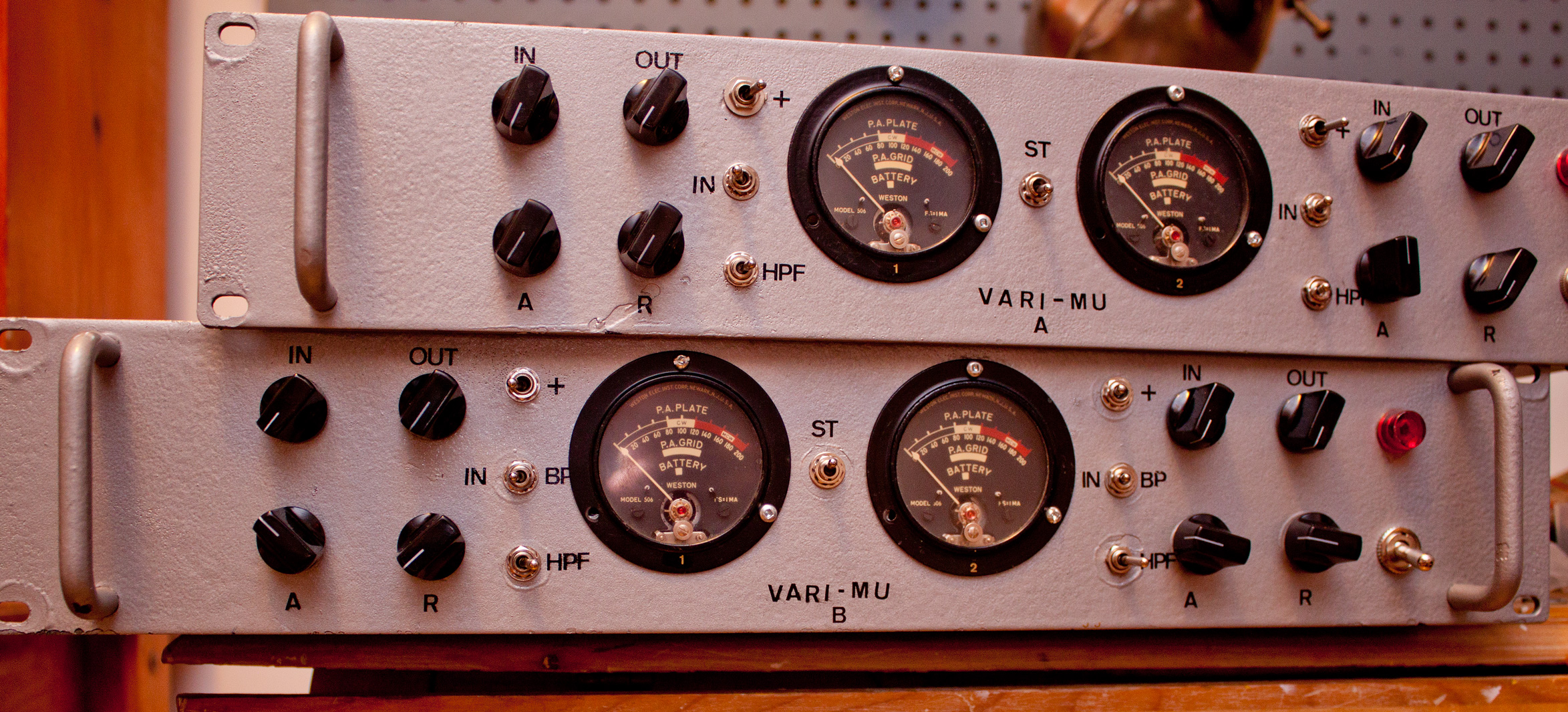
| March 18th, 2016We built a pair of PRR 176 stereo vari-mu compressors a couple years ago and we really love them. They’re maybe a little quirkier and less predicable than 1176 rev D FET limiters or LA2As, but on the whole they’re probably our favourite compressors–especially for vocals and clean guitars. They’re also very capable on stereo bus duty. Boards are no longer available for sale but un-built PCBs are frequently listed on the GroupDIY Black Market. We recently did a few modifications to our PRR 176s so I thought I’d do a writeup.
µ Oughta Know
Vari-mu, variable µ, or ‘tube’ compression is one of the major dynamic range compression circuit categories, the other main types being: Optical (LA2A); Diode Bridge (EMI TG12413, Neve 2254); FET (UREI 1176, early Allison Gain Brain); Pulse Width Modulation (Pye); and VCA (dbx 160, SSL, later Valley Gain Brain, most modern compressors). Each approach (and each circuit implementation) imparts its own sound though differing time constants, non-linearities and distortion products that are sometimes quite euphonic.
Prior to the invention of compression, dynamics were either controlled by manually adjusting levels or by performers positioning themselves nearer to or farther from the mic. Difficulties might arise with unpredictable talent: One thinks of the MGM crew charged with capturing the lion’s roar. Similarly, early Elvis Presley sessions allegedly employed an assistant to grab the King by his shoulders and physically vary his distance to and from the microphone based on musical dynamics. (Other reports say Elvis’s voice went through an RCA vari-mu compressor set to a gentle 2:1 ratio).

I believe vari-mu was the earliest electronic automatic gain control technology. Data are sketchy but as far as I can find, the Western Electric 110 compressor from 1937 is the first such unit. You can read a circuit description on page 563 of the December 1937 issue of Wireless World. Some say the Langevin Progar was developed earlier but took longer to come to market. Click here for a rough timeline of compressor development.
Unfettered Progress
The induction of the 1176 FET compressor in 1967 sounded the death knell for variable µ compression development. FETs are capable of faster attack times (which was crucial for the broadcast clients looking to get the loudest possible signal without over-modulating). The slower, more transparent optical compression technology cöexisted with vari-mu since the 1950s, but the new FET types (and the roughly contemporary diode bridge type) seemingly bested the old tube-based units in every important way: faster, quieter, wider control range, more reliable, and of course cheaper build costs. Thus development of new vari-mu types ground to a halt by the late 1960s.
Actual working engineers never quite gave up on tube compression. John Fry of Ardent studios called the Universal Audio 176 his compressor of choice for Radio City. And the Fairchild 670’s reputation grew to where it was probably the most coveted outboard gear unit in the world (last time I checked, they were going for $45K USD) .
Manley released their stereo Variable Mu compressor in 1994 (which I think was the first new major production tube compressor since they fell out of favour in the late-60s/early 70s). A few years later the Thermionic Culture Phoenix (supposedly based on the EMI-modified Altec 436) came out. Both of these units were very nice-sounding but neither differed much from vintage designs (not necessarily a bad thing but it made them very expensive).
Then in 2003, a guy who goes by PRR (don’t know his full name or background–I gather that he’s a professor of some sort) conceived a cheap-to-build modern vari-mu and gave his schematic and circuit description away for free. PRR’s design was a novel approach emphasizing the use of cheap, easily obtainable components (like ubiquitous 12AU7 tubes for gain reduction). As far as I can tell, his was the first to dispense with a vacuum tube side chain signal. Interestingly, Rein Narma, the Fairchild 660/670 designer, says in this interview that he’d have used a solid state side-chain if it was available to him.
Abe Chapman of AC Sound Studios came up with his circuit boards as a sort of cross between the PRR Vari-Mu compressor design and elements of the classic Universal Audio 175/176, such as employing a 6BC8 tube for gain reduction. Plus he added a few modern refinements, like: stereo or dual mono operation, bypass, and a switchable side-chain hi-pass filter (to reduce pumping when used on a stereo bus).
We didn’t tally the costs of building these compressors, but I’m quite sure it was under $2000 for all four channels. The priciest components were the audio transformers. Enclosures were probably the next most expensive items. We used budget, powder-coated steel 2RU cases with aluminum front panels. Working with steel is pure torture so I’d highly recommend getting an all-aluminum chassis if you can afford it.
Rev 1 Build Notes
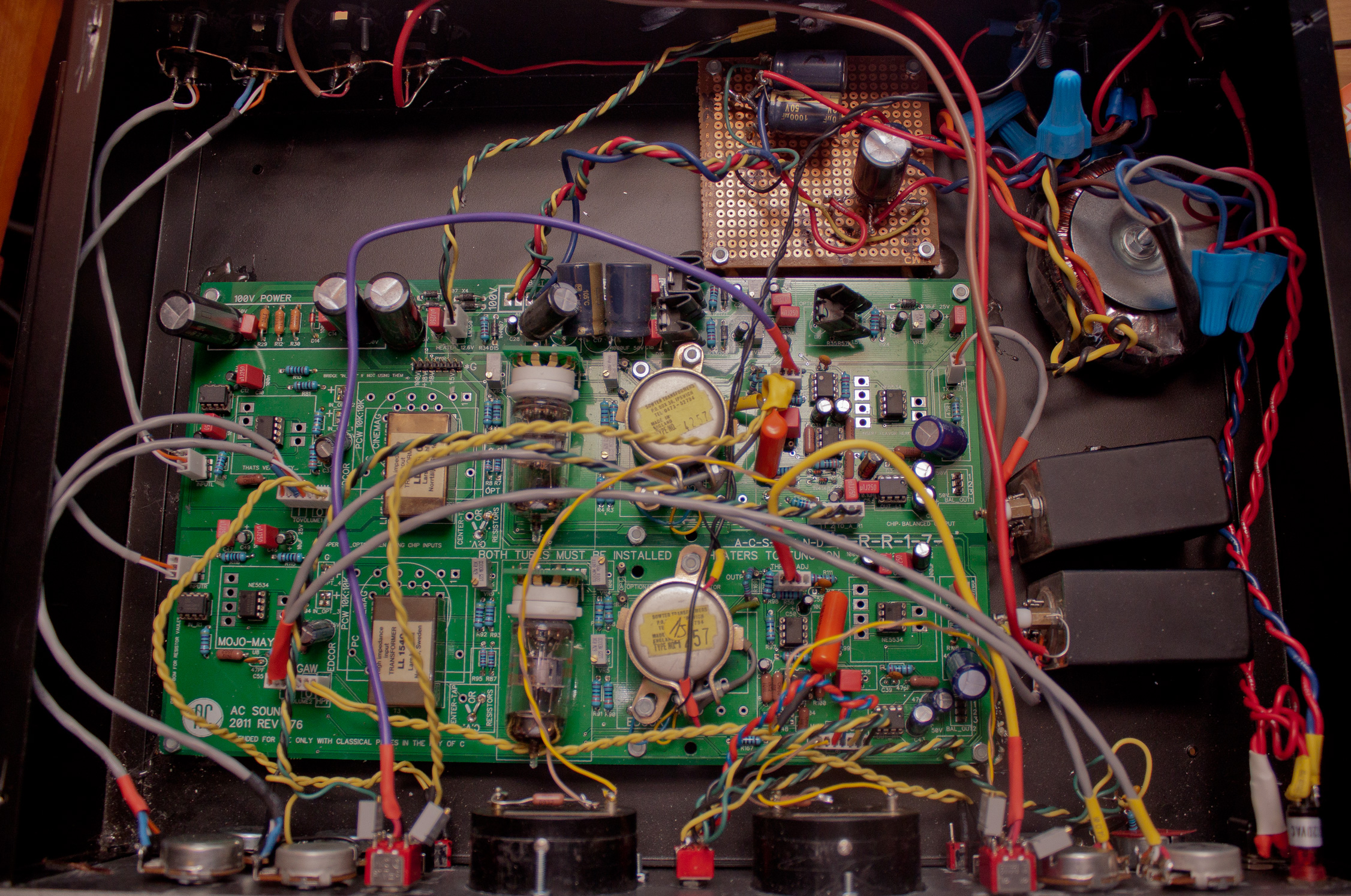
Abe’s first circuit board for the PRR 176 was already pretty well worked out. The only major problem was that the power supply on the main board would add noise to the circuit. The relatively easy work-around was building a simple Veroboard circuit for power supply rectification and filtering.
The circuit also lacked a bypass. This was relatively easy fix by lifting one leg of the side-chain capacitor and installing a front panel switch. Because this capacitor is in parallel with the side-chain high-pass filter cap, you need to engage the HPF switch for bypass to work. It’s a bit inelegant but it works. Note that this is a compression bypass, not a hard bypass. Hard bypass requires extra circuitry and relays. The advantage to this ‘soft-bypass’ approach is that you can use it as a line amplifier (e.g. extra clean gain after a mic preamp). The disadvantage is that you can’t do quick A-B comparisons between compressors.
For the Rev 1 we used Swedish Lundahl transformers for input; UK-made BBC/Sowter units for interstage (a really critical component for this compressor); and Canadian Hammond 1:1 600 ohm transformers for output. We initially used the optional IC balanced output but after some testing we decided we preferred the transformer outputs.
Everything worked quite well from the start except for the odd incident of thermal shutdown. We discovered that the tube filament regulator’s heat sink was inadequate. The fix was simple: mount the regulator IC to the case.
Rev 2 Build Notes
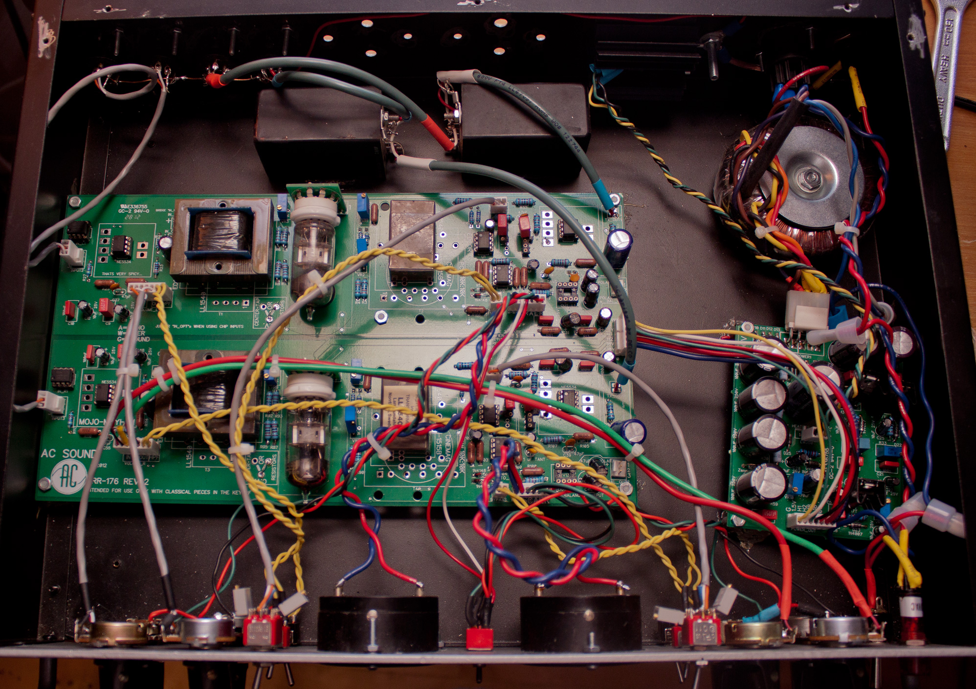
The Rev 2 PCB set provided a separate board for its power supply. Again everything went well right off the bat except for the tube filament regulator getting too hot (again, mounting it to the case fixed the problem).
For this unit, we used less expensive American-made Edcor input transfers, Lundahls for the interstage, and again Hammonds for the output. This transformer array gives a subtly different sound.
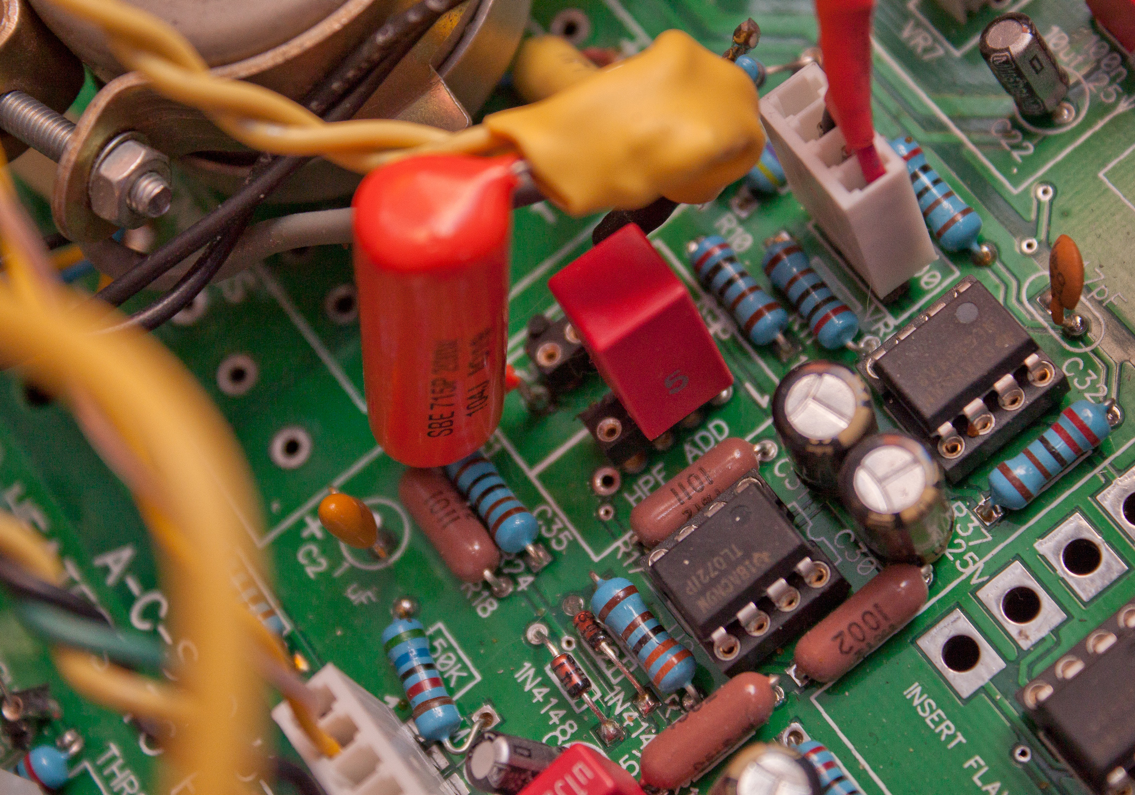
We socketed the capacitors for the side-chain high-pass filter in order to experiment with different values. We ended up liking Abe’s default choices (tho an extreme hi-pass made for an interesting de-esser effect).
Like the 176 and 1176, this compressor uses the input signal to set the compression threshold. We decided to do a simple modification to make this a bit easier to use in the real world. We fitted multi-turn trimmers to a switch and mounted them to the front panel and then ran the switch to the circuit board. This gives us a quick, calibrated high or low threshold (I’ve always found the 1176’s threshold impractically high for typical console ‘send’ levels). With stereo linking engaged, the circuit uses the channel 1 attack and release controls for both channels (input and output levels must be carefully matched for each side).
Calibration etc
The calibration procedure is pretty straightforward. Here’s Abe’s description:
Trimmers:
1k VR3, VR9 ….this balances the power between the 2 halves of the 6BC8 tube. Helps if you don’t have a perfectly balanced tube.
100R VR1,VR4 adjust for minimum “thump”
1k VR5, VR2 Control Meters, Power on, let it warm up for a bit (10 minutes or so) turn until meters read “0” gr.
There are a couple different ways to do the ‘thump’ calibration (which is, by far, the most crucial). The simple way is to feed a 20hz clean sine wave, dial in a decent amount of gain reduction and adjust for the least distorted waveform on an oscilloscope. A slightly more sophisticated approach is to feed the compressor gated bursts of high frequency (20KHz is good) and adjust for minimum thump. Here’s a good overview of both approaches.
We did encounter a several 6BC8 tubes had to be rejected because they weren’t balanced well enough to work in the circuit (so it’s wise to factor in the cost of buying some extra tubes). As you can see by the photos, we’re no experts at wire dressing but the compressor is very quiet and we’ve had no problems with oscillation despite the extra all the extra wiring from our modifications.
On our Rev 1, the meter calibration wouldn’t quite go to zero with our NOS Weston meters (found at Leeds Radio in New York).
The simple solution was to add a 1Kohm resistor in series.
We tried to measure the attack and release times with software but didn’t have much luck. The compression ‘knee’ is quite soft so it’s difficult to say when you’d deem it to be ‘in gain reduction’. It looks like it’s a bit faster than the 176’s 100 µsec attack time (but noticeably slower than the 1176’s 20µsec maximum) but I’d need to research measurement standards to know for sure. The settings aren’t fool-proof: even when well-calibrated, it’s possible to get some ‘thumping’ noise if the very fastest attack and release times are used on bass heavy material.
The front-panel finish was done with Tremclad ‘hammered finish’ spray-paint (a terrible product with noxious fumes and lumpy, inconsistent coverage properties) and the lettering done with old Decadry transfer sheets (an unbearably tedious job) and protected with clear nail lacquer (we tried two brands: ‘OPI Start to Finish’ which sucks and almost destroyed the already sketchy paint job; the other type called ‘Mavala top coat’ worked OK). If you hate metalwork as much as I do, circular Neutrik Powercon connectors are a small mercy to save yourself the agony of drilling a rectangle for a standard IEC inlet. Amateur metalwork generally involves breathing in nasty particulate matter, countless splinters, and hours of filing. If you can afford it you’d be best off getting Front Panel Express or a local engraver to finish your chassis.
Further reading
See the original build threads for much more information (including schematics, bills of materials, wiring guides, etc.)
PRR-176 Rev 4 Build Thread
In case you were wondering: there is no Rev 3.


 |
|
I recently heard one of these over at Pete Min’s place and was curious if there are others available. It sounded great!